Even in the era of artificial intelligence (AI), MRI artifacts can lead to interpretation mistakes or misdiagnoses, and it's vital for radiologists and radiographers to identify them, investigate their causes, and formulate a strategy to minimize or avoid them, award-winning researchers stated at ECR 2023.
"Many of them (artifacts) are automatically corrected on the latest devices during the acquisition preparation steps, or on the acquired signal thanks to artificial intelligence (AI) algorithms," noted Dr. Patricia Andrea Gutierrez from the Centre Hospitalier Dunkerque (CHD) and CHU de Lille, France. But artifacts remain a major headache, explained Gutierrez and colleagues in an e-poster that received a certificate of merit.
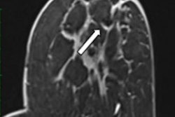
 Nonvoluntary movement artifact. Axial turbo spin echo, T2-weighted slice of the thorax with multiple replicas of the aorta (arrows) displayed on the phase-encoding direction, due to the vibration. The best strategy here is to invert phase and frequency directions in case of periodic artifacts. All images courtesy of Dr. Patricia Andrea Gutierrez et al and presented at ECR 2023.
Artifacts are defined as any part of an image that does not coincide with reality, according to the authors. They generate noise, cause distortion, and degrade image quality, and may have an impact on patient care. They can be classified as tissue, movement, or technical artifact, and they are numerous and multifactorial (e.g., magnet strength, objects in the room, Faraday cage effect, body part, physiology, and clinical state of the patient).
The growth of teleradiology and increased workloads mean that often radiologists are not present when images are acquired, but radiologists still have a responsibility to identify these artifacts as quickly as possible and give feedback to radiographers.
On their side, radiographers should not only prevent artifacts but also detect them, know the strategies to avoid or minimize them, and repeat corrected sequences if necessary, noted Gutierrez and co-authors Prof. Philippe Puech from Lille and Dr. Marcelo Pietrani and colleagues from the Hospital Italiano de Buenos Aires.
"Once an artifact is detected, internal or external factors must be identified to settle on the most suitable strategy," they explained.
Artifacts to watch out for
Magnetic susceptibility (or metal-induced) artifacts appear along air-tissue interfaces, near surgical implants or clips, or around metallic bodies or molecules such as deoxyhemoglobin.
Among the solutions are to remove ferromagnetic foreign bodies, avoid gradient echo and echo-planar sequences, and reduce voxel size, echo time, and water fat shift. Other strategies to consider are avoiding the use of fused light bulbs in the MRI suite room (use LEDs) because impurities in filament light bulbs can cause artifacts, switching patients to an MRI unit with a lower magnetic field strength, adjusting the chemical shift, and applying metal reduction algorithms such as O-MAR from Philips and WARP from Siemens Healthineers.
Dielectric effect, or standing wave effect, artifacts may be seen in cases of profuse ascites or in obese and pregnant patients, and it is due to the high magnetic field in a 3-tesla machine that can't maintain its homogeneity. Bright or dark "holes" in regions away from the receive coil caused by interference with the standing waves. These artifacts become more pronounced the larger the region of interest.
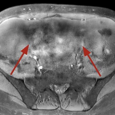
 Dielectric artifact. Axial echo gradient fat-saturated T1-weighted slice of the abdomen acquired on a 3-tesla device, showing multiple blurred areas of signal loss (arrows) at distance of the receiving coil, in a patient with abundant ascites. The strategy in this case would be first to apply parallel radiofrequency transmission technique, and if insufficient, to rescan the patient on a 1.5-tesla scanner.
"Pregnant patients should always be explored at 1.5T," the authors pointed out. "Ascites can be handled by switching to a lower magnetic field device or drained before the exam. Parallel radiofrequency (RF) transmission or any other technology improving RF emission homogeneity will reduce dielectric effects (e.g., Philips' MultiTransmit, Siemens' TimTx, GE's MultiDrive, Canon's Multiphase Transmit).
Communication with the patient is essential to avoid artifacts due to voluntary movements, they continued.
Ask patients not to contract their muscles during acquisition, explain acquisition phases, improve patient comfort within the MR tunnel (cushions, screens and mirrors projecting images, animations, etc), and use respiratory triggering and/or breath-hold techniques.
"Claustrophobia and stress can be managed with a small dose of benzodiazepines (in absence of contraindications). Hypnosis has also proved effective."
To avoid nonvoluntary artifacts can like bowel or ureteral peristalsis and cardiac pulsations or breathing, consider using an antiperistaltic drug (phloroglucinol/ trimethylphloroglucinol) invert phase and frequency directions in case of periodic artifacts (displaces them on the other axis), as they occur following the phase-encoding direction, reduce acquisition time, repeat the sequence (artifacts may appear outside of the region of interest), and apply AI postprocessing algorithms.
Technical artifacts
Technical artifacts such as aliasing occur when the diameter of the imaged object exceeds the field of view (FOV). This is due to a low bandwidth in the frequency-encoding direction, and it has a more complex cause in the phase-encoding direction. Anatomical structures located outside the FOV are mapped at the opposite end of the image.
To solve the problem, increase the FOV in the phase-encoding direction, change the direction of the phase-encoding gradient, and change the fold-over direction, Gutierrez and colleagues recommend.
The Gibbs ringing, or truncation, artifact is caused when using a too-small acquisition matrix, which generates an error of the Fourier transform. The solution is to repeat the scan with a larger phase-encoded matrix, a larger acquisition matrix, or a smaller FOV. The phase-encoding matrix should never be less than half of the frequency-encoded matrix, they noted.
 The Gibbs ringing effect. Sagittal T2-weighted image of cervical spine. Parallel bands-like areas of alternating high and low signal intensity occur at sharp transition edges of an object – in this case, the cerebrospinal fluid and the medulla (arrow).
The Zipper effect artifact is caused by external RF emission finding its way into the magnet room and being picked up by the receiving coils. This may be due to a break in the Faraday cage or the metallic shield built into the walls, floor, and ceiling of the scanning room. It appears as a line of alternating light and dark pixels, sometimes two or three pixels wide, extending across the image in the phase-encoded direction.
Using all monitoring materials adapted to MRI and closing the door are the most common solutions, the authors wrote.
Artifacts are caused by a variety of factors that may be patient-related, such as voluntary and physiologic motion, metallic implants or foreign bodies, according to Radiopaedia. Finite sampling, k-space encoding, and Fourier transformation may cause aliasing and Gibbs artifact. Characteristics of pulse sequences may cause black boundary, Moiré, and phase-encoding artifacts. Hardware issues may cause central point and RF overflow artifacts.
"Remember that artifacts are not all bad and that occasionally, they are intentionally exploited, e.g., susceptibility artifact," Radiopaedia notes.
To view the whole ECR 2023 poster, go to the EPOS section of the congress organizers' website.